
The combined resistance of n rod electrodes in parallel can be obtained from the following equations:
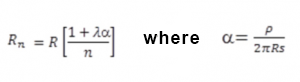
The above equations assume that rod electrodes can be represented approximately by hemispherical electrodes, having the same earthing resistance, located in
the soil surface. This assumption is satisfactory provided that the spacing between the rods is not less than their length.
If the rods are equally spaced in a straight line an appropriate value of λ may be taken from table 2.
For electrodes equally spaced around a hollow square, e.g. around the perimeter of a building, the equations given above are used with a value of λ taken from
table 3.
For three rods placed in an equilateral triangle, or in an L formation, a value of λ = 1.66 may be assumed.
The reduction in combined earth resistance provided by additional electrodes inside the square is small, but such electrodes will reduce the potential gradient
over the soil surface inside the square. A practical example of this is the use of strip electrodes forming an earth grid within the square.
Table 3 may also be used for electrodes arranged in a rectangle, where n is given by (total numer of electrodes/4) + 1. Provided that the lenght to width ratio
of the rectangle does not exceed 2, the error will be less than ‒ 6 %.
Table 1. Coeffcient for earth electrodes in a straight line | |
Number of electrodes | Coefficient |
2 | 1 |
3 | 1,66 |
4 | 2,15 |
5 | 2,54 |
6 | 2,87 |
7 | 3,15 |
8 | 3,39 |
9 | 3,61 |
Table 2. Coefficient for earth electrodes in the square | |
Number of electrodes | Coefficient |
2 | 2,71 |
3 | 4,51 |
4 | 5,48 |
5 | 6,14 |
6 | 6,63 |
7 | 7,03 |
8 | 7,36 |
9 | 7,65 |
10 | 7,9 |
12 | 8,32 |
14 | 8,67 |
16 | 8,96 |
18 | 9,22 |
20 | 9,4 |